
The Claus process is the most widely used technology for recovering elemental sulfur from hydrogen sulfide (H2S), an acid gas commonly generated in oil refining, natural gas processing, and coke oven gas treatment. In a sulfur recovery unit (SRU), H2S is converted to elemental sulfur through a combination of thermal oxidation and catalytic reactions, reducing sulfur emissions while recovering a valuable byproduct.
Efficient Claus unit operation depends on maintaining the stoichiometric relationship between H2S and sulfur dioxide (SO2). Deviations from the target H2S-to-SO2 ratio reduce sulfur recovery efficiency and can increase sulfur-containing emissions. Continuous and reliable measurement of these species in the tail gas is therefore essential for air-demand control, process optimization, and environmental compliance.
The Claus process
The Claus process comprises two principal steps. In the first step, known as the thermal step, approximately one-third of the incoming H2S is oxidized with combustion air in a reaction furnace to form SO2:
H2S + 3/2 O2 → SO2 + H2O
The reaction furnace typically operates at temperatures between 950 and 1500 °C. A significant fraction of the sulfur is already formed in the furnace. In the second step, which is catalytic, the remaining H2S and SO2 react to produce further elemental sulfur:
2 H2S + SO2 → 3/2 S2 + 2 H2O
This reaction takes place at much lower temperatures, typically between about 200 and 320 °C, depending on the catalytic stage and operating conditions. Because it is an equilibrium reaction, sulfur is condensed and removed from the gas stream after each stage, shifting the equilibrium toward sulfur formation. Two or more catalytic stages are arranged in series to increase the overall recovery.
Figure 1 shows a simplified schematic of a Claus SRU. The reaction furnace on the left is followed by a waste heat boiler and a series of condensers, in which the process gas is cooled below the sulfur dew point so that liquid sulfur can be drained off. The gas is then reheated before entering each catalytic reactor (converter), so that sulfur does not condense on the catalyst. In the converter, the reaction between H2S and SO2 continues, producing more elemental sulfur. The residual process gas leaving the final sulfur condenser is commonly referred to as tail gas.
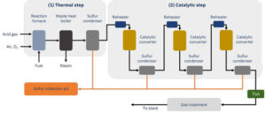
Figure 1. Schematic flow diagram of a Claus sulfur recovery unit.
Tail gas analysis
Emissions from the Claus process are directly linked to its recovery efficiency: the higher the efficiency, the less sulfur leaves the unit in the tail gas. As the reaction equation shows, conversion of H2S to sulfur is highest when H2S and SO2 are present in a stoichiometric ratio of 2:1. If this ratio deviates from the target, sulfur recovery decreases and sulfur-containing compounds in the tail gas increase. The main purpose of the tail gas analyzer (TGA) is therefore to provide the measurements required for air-demand control of the reaction furnace.
A commonly used air-demand control parameter is based on the deviation from the stoichiometric relationship, for example, [H2S] – 2[SO2]. A value of approximately zero corresponds to the target 2:1 H2S-to-SO2 ratio. Deviations can significantly affect SRU performance. Insufficient combustion air results in elevated H2S concentrations, while excess air increases SO2 formation. Both conditions reduce sulfur recovery efficiency and may lead to increased sulfur emissions. Continuous measurement of H2S and SO2 in the tail gas therefore provides the feedback necessary for accurate air-demand control, helping operators maintain optimal process performance and regulatory compliance.
NEO Monitors’ solution
The LaserGas™ analyzers from NEO Monitors are based on the well-proven technology of tunable diode laser absorption spectroscopy (TDLAS). TDLAS provides highly selective gas measurements by monitoring the absorption of laser light at gas-specific wavelengths.
Measurement of H2S and SO2 in SRU tail gas requires high selectivity because the gas stream contains multiple sulfur-containing species at varying concentrations.
The following LaserGas™ analyzers are recommended for this application:
Hydrogen sulfide (H2S):
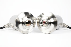
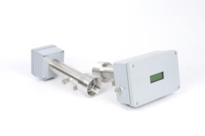
Sulfur dioxide (SO2):
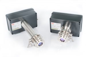
LaserGas™ products offer:
- High sensitivity and selectivity
- Fast response for real-time process control
- Contactless, in situ measurement
- Stable calibration with no zero drift
- Low maintenance requirements
- Long service life and high reliability
Advantages of TDLAS
Because TDLAS measures in situ, directly across the process duct, there is no need to extract, transport, or condition a gas sample. This eliminates sample probes, heated sample lines, filters, and other conditioning equipment that are susceptible to sulfur deposition and fouling. With no moving parts and no wear parts to replace, the analyzers can operate continuously in harsh process environments with minimal maintenance requirements. The result is high analyzer availability, reduced maintenance requirements, and fast, reliable measurements for precise air-demand control.
Installation recommendation
NEO Monitors recommends installing the analyzers with steam-heated insertion tubes, which keep the optical path above the sulfur dew point and prevent sulfur from depositing and blocking the laser beam. The steam circulates in a closed loop, so it never enters the customer’s process. For particularly demanding applications, a blowback system can be added to remove deposits and maintain a clear optical path.
Each mounting point is fitted with a ball valve. This allows the analyzers to be safely removed from the process for maintenance. The valve must be closed during blowback to protect the analyzers.
The bellows flanges, steam-heated insertion tubes and ball valves are supplied together as the ‘SRU installation kit’. One kit is required for each pair of nozzles.
NEO Monitors offers two installation options:
Option 1: Combined T-flange installation. When a LaserGas™ III SP is used for the H2S measurement, a T-flange allows both analyzers to share a single pair of nozzles, as shown in Figure 2. This minimizes nozzle requirements and simplifies installation. The option requires one SRU installation kit and one T-flange.
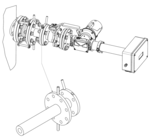
Figure 2. Combined T-flange installation, minimizing nozzle requirements and simplifying installation (Option 1).
Option 2: Separate installation. Each analyzer is installed on its own pair of nozzles, as shown in Figure 3. This allows H2S and SO2 to be measured at independent locations. The option requires two SRU installation kits.
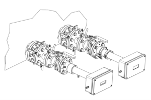
Figure 3. Separate analyzer installation for independent H2S and SO2 measurement locations (Option 2).
Further Information
Geiser and Avetisov, “Switching to in situ analysis”, Hydrocarbon Engineering, October 2018.
Application note: In Situ Tail Gas Analysis in Sulfur Recovery Units


